|
|
|
Harmonic Suppression Plan for PCB Production Lines
I. Background:
A Suzhou company has a PCB production line, in which the primary electric equipment comprises of high-power VFDs, rectification devices and other nonlinear loads. During operation, such loads generate a great amount of 5th and 7th current harmonics that will form voltage waveform distortion when affected by the system impedance, giving rise to switching malfunctions, fast attenuation and aging of capacitor sets, frequent damage of elements of compensation branches, harmonic contamination to the public grid through the point of common coupling (PCC), etc.
II. Data verification and analysis:
In accordance with GB/T14549-93 Quality of Electric Energy Supply: Harmonics in Public Supply Network and the results of site tests, the recommendations below are proposed against the harmonic suppression of the 4 power transformers:
1. Transformer TR1 is subject to severe harmonics. The 5th current harmonic under the fundamental current of 1,200 A has reached 210 A, far in excess of the limits of national standards. Based on what was learnt from the site, the total load current can reach up to around 1,800 A, which means the 5th current harmonic may increase up to 270 A approximately, resulting in an expected total harmonic distortion rate of voltage 5% greater than the limits of national standards.
2. The three main transformers TR2, TH4 and TH5 also suffered 5th current or a voltage out of limits. The existing regular capacitance compensation cabinet, when put to use, will give rise to parallel resonance with the system and lead to enlarged harmonic current, affecting the long-term stability of the electric equipment.
III. Methods for harmonic filtering and suppression:
1. From the results of site tests and the nature of loads,
it is recommended that:
For TR1 and TR4, the active power filtering method (WAPF) shall be used; and
For TR2 and TR5, the passive filtering method (WXL-A TSF passive filter) shall be used.
IV. Design of harmonic filter:
1. Primary technical indicators of filtering compensator (WXL-A TSF)
1.1 The filtering compensation system is connected to the secondary side of the rectifier transformer.
1.2 Absorption rate for 5th and 7th harmonic current shall reach over 70%, and the harmonic voltage of the corresponding sequence shall conform to GB/T14549-93.
1.3 Response time вүӨ 20 mS.
1.4. Average power factor of compensation вүҘ 0.95.
1.5 Voltage fluctuations in the grid during compensation comply with GB/T14549-93, i.e. the voltage fluctuation of the primary side as a result of variation from full to light load compensation вүӨ 2.5%.
1.6 The compensation system is provided with the following operation security measures:
System: overvoltage, overcurrent, undervoltage and grounding protection.
Capacitor: overvoltage, overcurrent, overheating and phase loss protection.
Inductance (reactance): overcurrent and overheating protection.
1.7 Total power consumption of compensation system: Ploss is smaller than 1.5% * Qtotal (where Qtotal is the total compensation).
1.8 The system generates no radio (radio frequency) EMI.
1.9 Operation mode: Fully automatic, operating continuously.
1.10 Displaying 11 kinds of data like Parameter, PF, U, I, S, Q, P and Working order.
2. Primary technical indicators of APF
(1) The LV dynamic APF compensator is an enclosed indoor equipment assembly used for dynamic suppression of harmonics and dynamic VAR compensation. It is able to compensate for harmonics with varying magnitude and frequency and unfixed var.
(2) The dynamic APF compensator shall employ technically mature components and is able to regulate output automatically in accordance with the variation in operation modes and fluctuations in loads of the grid, so as to offset the harmonics occurring therein.
(3) The dynamic APF compensator shall be independent (and free) from the impedance (and the effect brought by its variation) of both the grid and the system.
(4) The dynamic APF compensator is able to filter various harmonics from the 2nd to the 25th, with settable sequence and target value for the harmonics to be filtered.
(5) The dynamic APF compensator shall support unequal parallel expansion for future purpose. It shall be able to perform satisfying filtering and VAR compensation simultaneously.
(6) The filter shall avoid overcompensation while filtering, i.e. the dynamic APF compensator shall be capable of filtering without generating reactive power to prevent excessive compensation. Or, alternatively, the remaining energy after filtering shall be usable for VAR compensation by setting a power factor target.
(7) The dynamic APF compensator shall be provided with complete protective devices including ones for overload, overcurrent and short circuit, and system self-diagnosis function.
(8) In case of imbalance of three-phase load current, the dynamic APF compensator is able to maintain regular compensation and eliminate such imbalance.
(9) The device is provided with an open remote communication interface for connection with the monitoring system, so as to realize supervision on online power of the power supply system.
(10) The dynamic APF compensator shall be provided with a human-machine interface containing a LCD and operation buttons. The LCD and the operation panel shall be located on the surface of the assembly for easy access to parameter setting, status variation, information view, etc., and capable of displaying the operation conditions, measurements, malfunction alarms and other information.
(11) The high-frequency carrier of the dynamic APF compensator shall not be fed back to the grid, otherwise other systems or equipment might suffer disturbance.
(12) The control system of the dynamic APF compensator shall contain an arithmetic circuit for command current and a control circuit for current tracking. The arithmetic circuit for command current is mainly used to calculate and analyze the collected data and obtain the command signal. Control management on the dynamic APF compensator includes: programming filtering parameters, selection of multiple harmonics to be filtered, setting of priority of different functions, setting of power factor for VAR compensation, phase balance, and filtering with zero reactive power.
(13) The power supply of the device converts the input power to the control power required by the dynamic APF compensator itself. It normally comprises of transformer of incoming line, AC filter, switch power source, power panel and lightning protection element. Internal overload, overcurrent and short circuit protection for incoming lines are realized with circuit breakers or fuses. The device is fitted with internal overload, overvoltage, overheating, phase loss, short circuit, undervoltage of control and disturbance resistance protection and external output alarms and tripping ports.
(14) When the harmonic current in the system exceeds the rated capacity of the filter, it shall be able to withstand 200% overload without shutdown or damage.
(15) Overvoltage protection: to prevent overvoltage in the system, and lock the output of the dynamic APF compensator upon overvoltage and raise the corresponding alarm.
(16) Temperature protection: including overheating protection against the housing and the chip. Where the internal temperature exceeds the preset value, the output of the dynamic APF compensator will be locked and the alarm raised.
(17) Lightning protection: inside the cabinet provides a lightning protection element to prevent the filter from any damage caused by lightning stroke. An alarm shall be raised in case of a malfunction of the element.
(18) The device shall be able to supervise the parameters below (including but are not limited to):
1) Real-time supervision on filtering capability (percentage)
2) Content of fundamental waves of currents and harmonics of various sequences
3) Current distortion, frequency, etc.
4) Power factor
5) LCD: signals of grid voltage, current, current values of various harmonics, distortion rate of voltage, malfunction alarm, etc.
Operating principle:
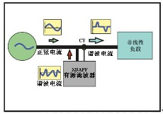
The active power filter (APF) is a new type of device specially developed for power filtering using modern power electronics and high-speed digital signal processing (DSP) technology. It mainly consists of an arithmetic circuit for command current and a generation circuit for compensation current. The arithmetic circuit for command current monitors the current in the lines in a real-time manner, and converts the current analog signals into digital ones and sends them to the high-speed DSP to separate harmonics from fundamental waves. Then, it will transmit drive pulses in the form of PWM signals to the generation circuit for compensation current to drive the IGBT power module, which will generate compensation currents with equal amplitude and opposite polarity to the harmonic current, and inject them into the grid to compensate or offset the harmonic currents, actively eliminating, and realizing the regulation on, power harmonics.

Characteristic of techniques:
Comprehensive functions: capable of simultaneously realizing functions of intelligent filtering of harmonics, dynamic VAR compensation and three-phase load balancing;
Excellent performance: provides almost perfect effect on harmonic filtering; continuous dynamic VAR compensation that increases the power factor to over 0.95; and ensures load balance and operation security of the equipment;
Advanced technology: capable of performing continuous, dynamic tracking and compensation; 40 Ојs to respond load changes, and 10 mS to complete compensation;
The filtering performance is free from the effect of system impedance,
so as to avoid serial or parallel resonance with it. On the contrary, it may even be able to suppress the existing resonance in the system.
V. Determination of total capacity of filtering compensation:
Formula: Q = P (
-
)
Based on the existing compensation capacity and in consideration of the harmonic filtering capacity, the compensation capacity of fundamental waves for filtering circuit is determined as follows through simulation calculation:
1. WAPF:
Transformer TR1 300 A (150 * 2 cabinets = 300)
Transformer TR4 200 A
2. WXL-A:
Transformer TR2 240 KVAr
Transformer TR5 320 KVAr
Determination of filtering compensation branches and distribution of fundamental capacity (WXL-A):
Transformer TR2:
6 filtering compensation branches, with 40 KVAr of fundamental compensation quantity for each;
Transformer TR5:
H5 1 filtering compensation branch, with 120 KVAr of fundamental compensation quantity;
H4 4 filtering compensation branches, with 50 KVAr of fundamental compensation quantity
и®ўйҳ…жҲ‘们жңҖж–°зҡ„ж¶ҲжҒҜ
ж–ҪдёҖз”ө气科жҠҖпјҲдёҠжө·пјүжңүйҷҗе…¬еҸё
е…ЁеӣҪз»ҹдёҖйЎ№зӣ®е’ЁиҜўзғӯзәҝпјҡ400-9202-119
ең°еқҖпјҡдёҠжө·еёӮеҳүе®ҡеҢәеҹҺеҢ—и·Ҝ1818еҸ·28ж Ӣ3жҘј
йӮ®зј–пјҡ201800
з”өиҜқпјҡ021-59967500/13761680509 дј зңҹпјҡ021-5996 8969
Email:ceayea@163.com
Http://www.ceayea.com