|
|
|
Power Quality Assessment and Solutions for LV Power Distribution System
I. Background
March 16, 2018, CEAYEA Electrical & Technology (Shanghai) Co., Ltd. was invited by a Jiangsu company to carry out a comprehensive test on quality of the site power, including 2 supply transformers of 10 kV/0.4 kV.
The test of the power quality on site was aimed at: via comprehensive tests, learning and identifying potential hazards in safe use of electricity; determining the elimination methods; and improving power quality, ensuring the safe, economic and long-term running of the system. The test results indicated the current problems, i.e. harmonics in significant excess of standards and poor power quality, which would lead to the following serious consequences:
1. The electric equipment would generate a great amount of harmonic currents that would eventually be turned into harmonic voltages by system impedance, resulting in significantly out-of-limit harmonics at PCCs and thus contaminating the public grid.
2. The harmonics would cause three-phase imbalance among the lines, cable heating, aging of cable insulation and even fires.
3. The harmonics would aggravate copper and iron loss, and result in overheating of transformers, reducing their actual output capacity.
4. The harmonics would increase the terminal voltage of the capacitors, giving rise to greater currents therein, accelerating the power consumption of the capacitors and resulting in abnormal heating, which will together age the insulating medium. Where the harmonics were severe, the capacitors might even swell up, break down or explode, leading to significant safety accidents.
5. Aggravating the additional wear of motors, reducing their efficiency, and even resulting in overheating of them. This would be particular true since harmonics of negative sequences would generate a rotating magnetic field of the same, causing torque in the opposite direction of the rotation, braking motors, compromising their output, and giving rise to overheating.
6. Harmonics would lead to overheating of switchgear, mistaken trip of switchgear or relay protection device, jeopardizing the operation stability of the production lines.
7. The existence of harmonic currents would lead to certain voltage ripples to the voltage of the busbar. The degradation of voltage quality would affect the power quality, and as a result, some measuring equipment would provide incorrect output or display, compromising safety and stability of equipment operation.
8. The food and beverage industries are of high production automation, hence harmonics might also affect them in the form of malfunctions of production equipment. This is especially true for highly precise equipment.
We will propose the solution to the problems mentioned above in accordance with the measurements on site and the analysis and assessment thereon.
II. Test results of power quality on site (simplified, see attachments for details)
1. Transformer 1# 2,500 kVA
Parameters of transformer
S11-2500kVAпјӣ 10/0.4kVпјӣ DYn11пјӣ
Power parameter
P/KW
S/KVA
Q/KVAr
COSРӨ
Remarks
1.13
1.13
69
0.97
Parameters of harmonics
I1
I5
I7
I11
I13
THDI
THDU
1827
213
55.8
22.8
---
11.9%
3.7%
2. Substation 2#
Parameters of transformer
S11-500kVAпјӣ 10/0.4kVпјӣ DYn11пјӣ
Power parameter
P/KW
S/KVA
Q/KVAr
COSРӨ
еӨҮжіЁ
63.8
66
16.8
0.97
Parameters of harmonics
I1
I5
I7
I11
I13
THDI
THDU
100
вҖ”вҖ”вҖ”вҖ”вҖ”вҖ”вҖ”вҖ”вҖ”вҖ”вҖ”вҖ”вҖ”вҖ”
18.7
1.6%
Analysis and suggestions:
1. Assessments and suggestions
S/N
Location
Transformer number
Compliance of harmonics
Compliance of power factor
Recommen-dations
1
Power Distribution Room
2500KVA
Seriously overproof
Up to standard
Control required
2
Power Distribution Room
500KVA
Up to standard
Up to standard
Control
unnecessary
2. Basis of assessments
Basis of assessments: GB/T14549-93 Quality of Electric Energy Supply: Harmonics in Public Supply Network. See Table 1 for harmonic voltages (phase voltages) of public grids specified by GB/T14549-93 Quality of Electric Energy Supply: Harmonics in Public Supply Network:
Table 1
Nominal voltage of grid
KV
Total harmonic distortion rate of voltage
%
Content of each harmonic voltage,%
Odd
Even
0.38
5.0
4.0
2.0
6
4.0
3.2
1.6
10
35
3.0
2.4
1.2
66
110
2.0
1.6
0.8
The harmonic current allowed to be injected to the grid by each user on the PCC is allocated as per the proportion of the userвҖҷs protocol capacity at that point to the capacity of the PCC power supply. See Appendix C (supplementary) for calculation of allocation.
3. Assessment description
3.1 The test involved 2 transformers of the 0.4 kV power system, and all the data were obtained with the VAR compensators absent. The primary load properties of the 2 transformers: extremely high power factor as a result of high production automation and the use of VFDs. However, the content of harmonics was significantly out of limit. For the 2,500 kVA transformer, the 5th harmonic current was as high as 213 A, and the 7th one was about 60 A. The distortion of harmonic current was as high as 11.7% with serious background harmonics. Therefore, regulation was necessary. The influence on quality of the grid was even aggravated by the background harmonics. Additional filtering compensation equipment is recommended for suppression of system harmonics.
III. Harmonic suppression plan
In accordance with the test results on site and the relevant analysis, the power system of the tested 1 transformer was subject to severe power quality issue, featuring in high power factor and harmonics. With the background harmonics, this would impose far worse effect on the grid quality. Hence the comprehensive regulator for power quality is recommended.
1. Aims and demands:
1.1 The effect of the device complies with YD_T2323-2011 Active Power Filter;
1.2 No harmonic amplification or system resonance will occur when put to use;
1.3 When put to use, the three-phase imbalance will be mitigated and the voltage fluctuations comply with GB12326-2000 Power Quality - Voltage Fluctuation and Flicker;
1.4 The harmonic parameters of the PCC test points fulfill the requirements of GB14549-93 Quality of Electric Energy Supply: Harmonics in Public Supply Network. Distortion rate of voltage THDU < 5%;
1.5 Damage by harmonics to the power distribution system will be reduced, and the power quality improved.
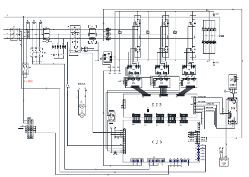
2. Plan of primary wiring:
3. Main technical parameters:
3.1 Harmonics compensation quantity
S/N
Transformer number
Compensation capacity
Qty.
Remarks
1
2500KVA
300A
1 cabinet
75Amodule
*4
3.2 Main Technical Indexes
в—ҸRated working voltage: AC380 Вұ 15%;
в—ҸRated working frequency: 50 Hz Вұ 5%;
в—ҸScope of filtering: 2 - 50 sequences;
в—ҸFiltering capability: вүҘ85%;
в—ҸSwitching frequency: 21.6 kHz (average);
в—ҸFull response time: вүӨ 40 mS;
в—ҸOverload capability: 120%;
в—ҸProvided with complete protective functions: overload, overcurrent, overvoltage and fault self-diagnosis.
4. Technical characteristics
4.1 Employing tri-level technology with the following advantages:
в—ҸThe switching loss of a tri-level converter is significantly lower than a bi-level one.
в—ҸGood conduction and switching characteristics.
в—ҸQuality output waveform, small ripple current and high efficiency.
в—ҸIn a tri-level inverter circuit, the DC voltage U is shared by two switching devices. Switches on each bridge arm are subject to a voltage half as much as the input voltage at the DC side.
4.2 Highly expandable:
в—ҸThe 300 A filter cabinet comprises of 4 Г— 75 A modules, and each of such cabinets has the ability to accommodate up to 6 modules.
в—ҸWhere any of the modules malfunctions, the rest will remain unaffected.
в—ҸConvenient for both site expansion and maintenance.
5. Determination of harmonic compensation capacity
The capacity of the transformer was 2,500 kVA, the load rate 51.4%, the total current 1,856A, and the current distortion rate 11.9%. The harmonic currents in the power system were significantly out of limit with the 5th and 7th being the predominant sequences. Considering the load rate of the transformer, it is suggested to provide the transformer in the distribution room with an APF for harmonic suppressing to improve conditions of power use and the safety and reliability of the power system.
Recommended configuration: A set of 300 A APF.
и®ўйҳ…жҲ‘们жңҖж–°зҡ„ж¶ҲжҒҜ
ж–ҪдёҖз”ө气科жҠҖпјҲдёҠжө·пјүжңүйҷҗе…¬еҸё
е…ЁеӣҪз»ҹдёҖйЎ№зӣ®е’ЁиҜўзғӯзәҝпјҡ400-9202-119
ең°еқҖпјҡдёҠжө·еёӮеҳүе®ҡеҢәеҹҺеҢ—и·Ҝ1818еҸ·28ж Ӣ3жҘј
йӮ®зј–пјҡ201800
з”өиҜқпјҡ021-59967500/13761680509 дј зңҹпјҡ021-5996 8969
Email:ceayea@163.com
Http://www.ceayea.com